Product TOP
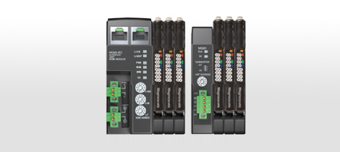
Interface unit for Tough Sensor series. Output data from DF800S series can be calculated and controlled by PLC via EtherCAT/CC-Link fieldbus. DT series (general purpose type) can be connected by using MT20-01/05 series interpolator.
- MG50-EC (EtherCAT) / MG50-CL (CC-Link)
- Fieldbus compatible main module interface unit. Maximum of 30 gauges can be connected to MG50-EC (maximum of 16 gauges for MG50-CL).
- MG51
- Distribution module for MG50. When installing digital gauges over a long distance, extension cables aren’t required when using a MG51. Ten gauges can be connected per unit. Maximum cable length is 30 m.
- MF10-CM
- Counter module for DF800S series. MF10-CM is compatible with the MG50/51 series.
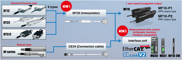
- Digital tolerance indicator for DF800S series digital gauges. 2 clicks to set the threshold value.
MF10-P1 : NPN output (current sink)
MF10-P2 : PNP output (current source)
Specifications
| MG50 series Specifications | ||||
|---|---|---|---|---|
|
Magnescale reserves the right to change product specifications without prior notice. |
||||
| Model | Main module | Distribution module | ||
| MG50-EC | MG50-CL | MG51 | ||
| Commnication protocol | EtherCAT | CC-Link | Data transferred to main module by dedicated protocol | |
| Baud rate | 100 Mbps | Maximum downlink speed of 10 Mbps | – | |
| Node address setting method | Set with decimal rotary switches or software | Set with decimal rotary switches | – | |
| Node address range | 000 to 192 | Max. 64 | – | |
| Maximum connectable counter modules | 30 | 16 | 10 | |
| Maximum connectable distribution modules | 8 | – | ||
| Maximum cable length | Maximum cable length between main module and distribution module: 30 m | |||
| Mounting method | 35 mm DIN rail mounting | |||
| Power supply | DC 24 V (20.4 to 26.4 V) | |||
| Power consumption / Current consumption (main unit only) | 2.4 W or less 100 mA or less (at DC 24 V) | 2 W or less 80 mA or less (at DC 24 V) | ||
| MF10 series Specifications | ||||
|---|---|---|---|---|
|
Magnescale reserves the right to change product specifications without prior notice. |
||||
| Model | Digital tolerance indicator | Counter module | ||
| MF10-P1 | MF10-P2 | MF10-CM | ||
| Function | NPN output (current sink) | PNP output (current source) | Counter module for MG50 | |
| I/O | Number of Go/No Go judgement output 2, Number of external inputs 1 Load voltage: DC 30 V or less, open collector output type Load current: the total of the two outputs must be 100 mA or less Residual voltage and load current less than 10 mA: 1 V or less Load current 10 mA to 100 mA: 2 V or less Off-state current: 0.1 mA or less |
– | ||
| Minimum display unit | 0.1 µm | |||
| Cable length | input/output, power cable 2 m | – | ||
| Mounting method | 35 mm DIN rail mounting | |||
| Power supply | +10 to +30 V DC including ripple (p-p) 10 % | |||
| Power consumption / Current consumption | 2.1 W or less / 85 mA or less | |||
Catalog
Please refer to the Digital Gauge General catalog.