Product TOP
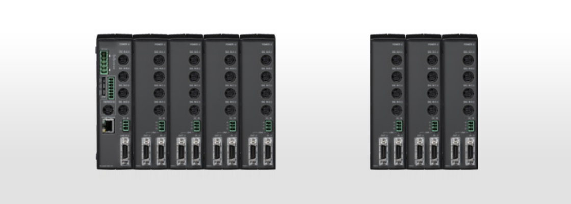
MG40 series, new measurement system integrates the primary functions of a counter into the gauge itself to a high degree. The MG40 series does not have to count analog outputs or AB phase outputs of the gauge and acquires positional information directly via full digital communication. The theoretical response speed is 20 times faster than the response speed of our previous models. Miscounts, caused by external noise, are eliminated and the system is capable of instantly recovering from a communication error by way of re-reads.
- High-speed and highly reliable communication shortens cycle times
- High-speed communication via Ethernet
- Communication error detection
- High-speed RISC processor dedicated to communication
- Our proprietary high-speed processor for multi-axis data processing
- Newly developed ASIC
- Quick and simple wiring connections
- Connection via a hub
- PLC connections
- Power supply
- Acquiring individual gauge information
- DIN rail mount and frontal connections
- Maximized system efficiency
- On the path to a revolution in quality
- High-speed measurements enable shorter cycle time
- Lower overall system costs
Specifications
| MG41-NC Series Specifications | ||||||||
|---|---|---|---|---|---|---|---|---|
| Item | Conditions | Description | Remarks | |||||
|
Magnescale reserves the right to change product specifications without prior notice. |
||||||||
| No. of connectable measuring units | Entire system | 1 to 100 units (Connection disabled aft er connection of 101st unit.) | Up to 24 connected MG42 hub units | |||||
| MG41 main unit | 0 to 4 units | |||||||
| MG42hub unit | 0 to 4 units | |||||||
| Connectable measuring units | DK800S series, DK series | |||||||
| Connection cable length | Between MG41 main unit and MG42 hub unit, and between MG42 hub unit and MG42 hub unit : 0.5 m, 1 m, 2 m, 5 m, 10 m Total cable length from MG41 main unit: Maximum 30 m (Maximum current: 4 A or less) |
|||||||
| Maximum resolution | Settable output data resolution and display resolution | |||||||
| Measuring units resolution (input resolution) | 0.1 µm | 0.1 µm | 0.5 µm | 1 µm | 5 µm | 10 µm | ||
| 0.5 µm | – | 0.5 µm | 1 µm | 5 µm | 10 µm | |||
| Measuring unit data import capacity | data transfer 10 Mbps | Max. 10000 data/s (when 100 axes are connected) | The data for one axis is counted as one data. | |||||
| Peak hold function | Calculates the maximum, minimum, and P-P values for each axis (pause, latch, and start functions available) | |||||||
| Peak value is not updated during pause. | ||||||||
| Output and display data are not updated during latching (internal data is updated) | ||||||||
| Recalculation of peak value is started by start function. | ||||||||
| Output data | Single axis | Current value, maximum value, minimum value, and P-P value of each axis | ||||||
| Addition and subtraction | Current value, maximum value, minimum value, and P-P value of the two addition / subtraction axes | Single axis calculation of an addition / subtraction axis is not possible. | ||||||
| Conparetor function | Compares and measures the data of each axis (single axis, addition / subtraction axis) and outputs the comparator result (when latched, the comparator is also latched). | |||||||
| Comparator setting values | 2 values | 4 values | 8 values | 16 values | ||||
| No. of setting value groups | 16 groups | 8 groups | 4 groups | 2 groups | ||||
| Ethernet | 100Base-T (compliant with IEEE 802.3) 100 Mbps/10 Mbps/1 Mpbs (Auto-negotiation) command input, data output and parameter setting available | |||||||
| Reset function | Current value for each axis is reset (by command). | |||||||
| Preset function | Value is preset to the current value of each axis (by command). | |||||||
| Datum point setting function | Datum point of each axis can be set (by command). | When master calibration function is not used | ||||||
| Reference point function | Reference point can be used to relocate the datum point of each axis (by command). | |||||||
| Master calibration function | Reference point can be used to perform master calibration for each axis (by command). | |||||||
| Measuring unit product information | The product information of the connected measuring unit can be acquired (by command): product code/serial number/manufacture date | |||||||
| Command/setting enabled or disabled for each communication line | Ethernet | CC-Link | ||||||
| Command | Reset function | ○ | ○ | |||||
| Preset function | ○ | ○ | ||||||
| Datum point setting function | ○ | ○ | When master calibration function is not used | |||||
| Reference point function | ○ | ○ | ||||||
| Master calibration function | ○ | ○ | ||||||
| Comparator value setting | ○ | ○ | ||||||
| Comparator group number setting | ○ | ○ | ||||||
| Start | ○ | ○ | ||||||
| Pause | ○ | ○ | ||||||
| Latch | ○ | ○ | ||||||
| Data output | Current value・Peak value (all axis) | ○ | × | |||||
| Current value・Peak value (each unit) | ○ | ○ | ||||||
| Comparator result | ○ | ○ | ||||||
| Alarm (data transfer・measuring units) | ○ | ○ | ||||||
| Software version | ○ | ○ | ||||||
| Measuring unit product information | ○ | ○ | ||||||
| Various settings | Input resolution | ○ | ○ | |||||
| Display・output resolution | ○ | ○ | ||||||
| Axis addition | ○ | ○ | ||||||
| Comparator mode (2, 4, 8, or 16 values in 1 group) | ○ | ○ | ||||||
| Power supplyPower supply voltage | Terminal input | DC12 to 24 V (11 to 26.4 V) | Use a power supply with a current that is 4 A or higher. (Recommended: +24 V) (for every six MG42 hub units) | |||||
| Power consumption | Note the connection conditions. | System total : Max. current 4 A | ||||||
| If the maximum current is exceeded, it can be connected to a subsequent MG42 hub unit by supplying power to it. | ||||||||
|
Power consumption breakdown for each unit MG41 main unit : 4 W MG42 hub unit : 1 W/unit Measurement unit supply : 1 W/unit |
||||||||
| Operating temperature/humidity | 0 to +50 °C (non condensing) | |||||||
| Storage temperature/humidity | -10 to +60 °C (20 to 90 %RH) | |||||||
| Mass | MG41 : 300 g MG42 : 250 g | |||||||
Dimensions
Catalog
| MG40 Series | Japanese |  |
|---|---|---|
| MG40 Series | English | |